
UART SERIAL COMMUNICATION BASICS DRIVER

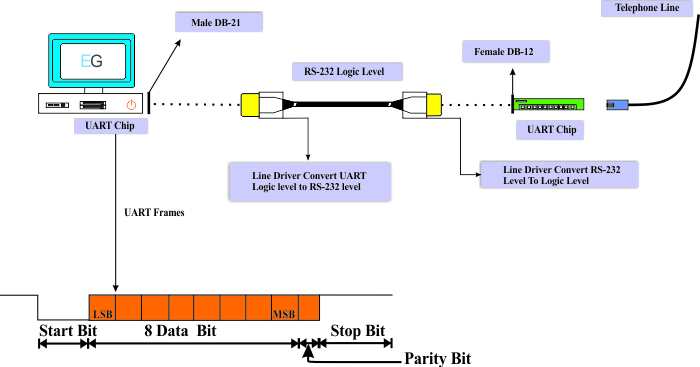
Logic level ‘0’ is shown as ‘1’ and Logic level ‘1’ is shown as ‘0’. The RS232 signals are represented as inverted logic. So in an 8-bit binary format, it is 0100 0001. For instance, an ASCII value for a character ‘ A‘ in RS232 is 65 and 41 in Hexadecimal. In most cases RS232 levels range from -12V to +12V. RS232 Logic: RS232 Voltage Levels Logic Level Here are the voltage levels for RS232 and TTL.

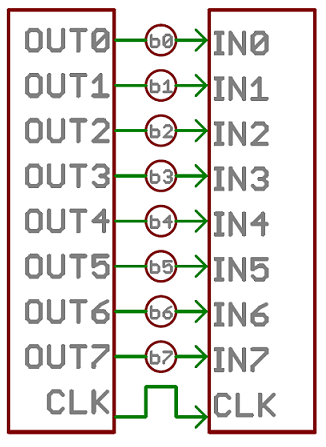
Logic levels represent the operating voltage levels that a device can withstand to operate in a safe zone. Handles serial communication during high energy consumption The baud rate should be known before transmission. Supports multiple protocols like LIN, RS-485, IrDA, Smart Card etc. The data rate is higher due to external clock. The sending device will generate the clock. The Clock is generated internally by the microcontroller. For easy understanding, here is the comparison between USART and UART. The main difference between UART and USART is, UART supports only asynchronous communication, whereas USART support synchronous as well as asynchronous communication. These are microcontroller peripherals that convert parallel data into serial bits and vice versa. But, the definition is the same for both of them. Working of D – Flip-flopĮSP8266 Commands – Docklight Program UART vs USART Generally, D flip-flops or latches are used to design the converters. For example, we have 4-bit data, to convert it into the serial form, we need a parallel to serial converter. In short, transmitter and receiver use start bit, stop bit, and timing parameters to synchronize with each other. To know the working of UART, you need to understand the basic functionality of serial communication. Devices like GPS and GSM use slower baud rates in 48. Mostly, microcontrollers come up with higher baud rates such as 11520 for faster data transfer.
UART SERIAL COMMUNICATION BASICS GENERATOR
The baud rate generator generates speeds ranging from 110 bps (bits per second) to 230400. In addition to these, a read or write control logic is provided to tell when to read/write. The transmit shift register and receiver shift register shift the bits to the left or right until a byte of data is sent/received. The Transmit hold register contains the data byte to be transmitted. The baud rate generator generates the speed at which the transmitter and receiver have to send/receive the data. It requires a single wire for transmitting the data and another wire for receiving. It is a cheap communication device with a single transmitter/receiver. When the high-speed data transfer is not required UART is used. Protocols like SPI (serial peripheral interface) and USB (Universal Serial Bus) are used for fast communication. This data is present in modulating form and transmits at a defined baud rate. An 8-bit serial data received from the peripheral device is converted into the parallel form using serial to parallel conversion and parallel data received from the CPU is converted using serial to parallel conversion.

The function of UART is to convert the incoming and outgoing data into the serial binary stream. It is a hardware peripheral that is present inside a microcontroller. “UART” stands for Universal Asynchronous receiver-transmitter.


 0 kommentar(er)
